Appendix C: UNC-Chapel Hill Bicycle Facility Design Approach
This appendix provides an overview of the guidelines and standards applicable to designing bicycle facilities on the University of North Carolina – Chapel Hill (UNC-CH) Campus. Following these standards and guidelines will allow UNC-CH staff to work with Town of Chapel Hill and North Carolina Department of Transportation staff to move forward with confidence that what they are doing is consistent with the latest thinking on safely accommodating bicycles.
AASHTO Guide for the Development of Bicycle Facilities (AASHTO Bike Guide)
The American Association of State Highway and Transportation Officials (AASHTO) is a not-for-profit, nonpartisan association representing state highway and transportation departments. It publishes a variety of planning and design guides, including the AASHTO Bike Guide.
The “Guide” is not intended to set absolute standards, but rather to present sound guidelines that will be valuable in attaining good design sensitive to the needs of both bicyclists and other roadway users. The provisions in the Guide are consistent with and similar to normal roadway engineering practices. Signs, signals and pavement markings for bicycle facilities should be used in conjunction with the MUTCD.
Key provisions in the AASHTO Bike Guide include:
- Bicycle planning, including types of planning processes, technical analysis tools and integrating bicycle facilities with transit
- Bicycle operation and safety, including traffic principles for bicyclists and causes of bicycle crashes
- Design of on-road facilities
- Design of shared-use paths
- Bicycle parking facilities
- Maintenance and operations
MUTCD, 2009
The 2009 MUTCD is a document issued by the Federal Highway Administration (FHWA) of the U.S. Department of Transportation (USDOT) to specify the standards by which traffic signs, road surface markings and signals are designed, installed, and used. These specifications include the shapes, colors, font sizes, etc., used in road markings and signs. In the United States, all traffic control devices must generally conform to these standards. The manual is used by state and
local agencies and private design and construction firms to ensure that the traffic control devices they use conform to the national standard.
The National Committee on Uniform Traffic Control Devices (NCUTCD) advises the FHWA on additions, revisions and changes to the MUTCD. The NCUTCD also evaluates research reports for experimental traffic control treatments to determine the suitability or need for developing changes to the MUTCD.
Key provisions of the 2009 MUTCD related to bicycling include:
- Bicycle-related regulatory and warning signs
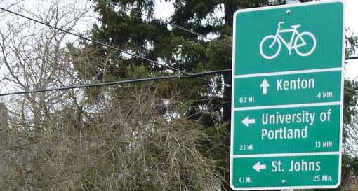
- Bicycle destination guide and route signs
- Pavement markings such as bike lane symbols and striping
- Shared-use path signs
- Shared-lane pavement markings
The bicycle technical committee of the NCUTCD is currently developing and evaluating research and proposals for the following items:
- Bicycle signals (FHWA interim approval December 2013)
- Bicycle boxes (approved June 2014)
- Applications of the Rectangular Rapid Flashing Beacon to Trail Crossings
- Combined right turn lane/bike lanes
- Barrier separated lanes/cycle tracks
National Association of City Transportation Officials (NACTO) Urban Street Design Guide and Urban Bikeway Guide
The National Association of City Transportation Officials (NACTO) has developed Urban Street and Bikeway design guidelines which are tailored to the unique constraints and needs of urban areas. The guidelines are compendium of state-of-the practice techniques designed to result in high quality, multi-modal communities. The guidelines are based on current research and applied experiential practice of urban design professionals from around North America. The guidelines are freely available and regularly updated through their respective websites:
Bicycle & Pedestrian Project Development & Design Guidance
NCDOT’s Division of Bicycle and Pedestrian Transportation (DBPT) is the oldest program of its kind in the nation, established in 1973. DBPT seeks to integrate bicycle and pedestrian safety, mobility and accessibility into the overall transportation program through engineering, planning, education and training. The bicycle facility design guidelines were developed in 2004 and as such are not as current as the AASHTO Guide or the NACTO guide.
2009 North Carolina Supplement to the MUTCD (NCSMUTCD)
State agencies are required by federal law to develop a State level MUTCD that substantially conforms to the federal MUTCD. The NCSMUTCD explains which provisions of the Federal MUTCD have been modified by North Carolina statute.
NCDOT Complete Streets Policy
The NCDOT adopted a “Complete Streets” policy in July 2009. The policy directs the NCDOT to consider and incorporate several modes of transportation when building new projects or making improvements to existing infrastructure. The benefits of this new approach include:
- Making it easier for travelers to get where they need to go;
- Encouraging the use of alternative forms of transportation;
- Building more sustainable communities;
- Increasing connectivity between neighborhoods, streets and transit systems;
- Improving safety for pedestrians, cyclists and motorists.
Town of Chapel Hill
Bicycle Parking Guidelines
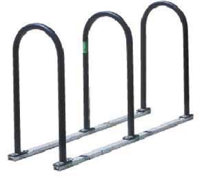
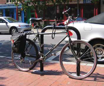
The Town has adopted the APBP Bicycle Parking Guidelines as a standard reference for the planning, location and design of bicycle parking.
Bicycle Facility Guidelines
The Town of Chapel Hill Bicycle Facility Guidelines were developed by Town staff and contain specifications and designs for on-street bike routes, on-street bike lanes, bicycle-related signs and intersections of shared use paths with public and private streets. They are integrated into the Town Design Manual (2005) and standard details. These standards and guidelines are not as current as the AASHTO Bike Guide or the NACTO guide.
The motorist operates within a protected, crashworthy shell which is insulated and protected from the outdoor environment. The motor vehicle is capable of rapid acceleration and can maintain constant rates of speed, with suspension systems capable of moving the vehicle over surface irregularities relatively smoothly.
The bicycle and the bicyclists function and experience traveling in relatively the opposite manner. In mixed traffic, the bicyclist is particularly sensitive to traffic noise, pollution speed and acceleration differentials. Poor surface conditions which can create crash hazards and result in increased exposure to injury or death in the event of a crash. Compared to other roadway users, bicyclists and pedestrians are the most vulnerable users in the transportation system.
Bicyclists also enjoy a number of significant advantages over the motorists in that they operate with greater freedom of movement, are less likely to be distracted while operating the bicycle and are more aware of their surroundings by being in the open environment.
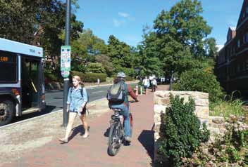
Preference surveys and research studies have found widespread support and interest for bicycling with strong preferences given to the provision of high quality bikeways which provide the following elements:
- Separation from high volumes of fast-moving automobiles,
- Maneuverability within the bikeway to operate safely,
- Space for cyclists to ride together in a social manner, side-by-side.
These qualities are routinely provided on trails and are increasingly provided on streets through the provision of bicycle lanes, cycle tracks or the implementation of bicycle boulevards. The quality of provided bicycle facilities has a direct impact on the experience of the bicyclists and will therefore have a tremendous influence on the ability of the facility to sustain use or to attract increased use. Well-maintained and high quality facilities have been demonstrated to attract higher levels of use than poorly maintained or low quality facilities. Likewise, interconnected systems with minimal gaps or interruptions are essential to a functioning bicycle system that supports and attracts high use as evidenced in cities such as Boulder, Charlottesville, Charlotte, Portland, Seattle and Washington, DC.
The concept of level of service for bicyclists is relatively new compared to that of vehicle level of service concepts. As such, it is important to note that there are limitations to the existing models which the designer should become familiar with. It is anticipated that extensive research will be forthcoming to improve the reliability of the measurements now that the concept has been validated and incorporated into the HCM and the AASHTO Guide.
An example of Bicycle Level of Service is provided in the table below comparing theoretical retrofit cross sections for a typical 6 lane arterial street. This example illustrates the value of a combination of narrower vehicle lanes and wider bicycle lanes in creating a more comfortable bicycling environment; however the ability to provide a high quality level of comfort is limited by the higher traffic speeds and volumes in the adjacent lanes.
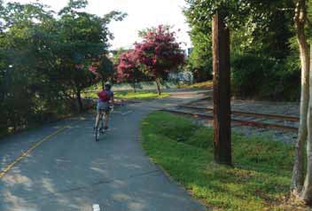
A similar quality of service exists 2 for trails where bicyclists with varying levels of skill are frequently operating in mixed use with pedestrians, joggers, rollerbladers and dog walkers. Speed differentials and group behavior dynamics (pedestrians and bicyclists) affect the available operating space of the bicyclist potentially limiting their ability to move at normal desired operating speeds.
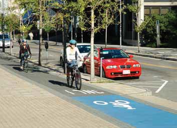
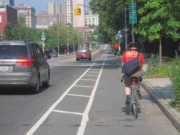
There are also numerous safety and comfort benefits which can be provided to bicyclists by providing wider bicycle lanes. Wider bicycle lanes create space for bicyclists to pass other bicyclists with more comfort, create additional buffer space to parked vehicles (and opening doors), create additional maneuvering space to avoid surface defects or hazards and allow bicyclists to operate side by side if desired. The graphic on the adjacent tab illustrates the comparative operating differences.
1 Bicycle Level of Service is an evaluation of bicyclist perceived safety and comfort with respect to motor vehicle traffic while traveling in a roadway corridor. It has been incorporated into the 2010 HCM. The research is more highly developed for mid-block segments than for intersection nodes.
2 Chapter 23. Highway Capacity Manual. 2010.
| Outside Travel Lane Width | Shoulder/Bicycle Lane Width to Left of Gutter Seam | Resulting Bicycle Level of Service (LOS Score) |
|---|---|---|
| 16 | 0 | D (4.29) |
| 15 | 1 | D (4.29) |
| 14 | 2 | D (4.29) |
| 13 | 3 | D (3.76) |
| 12 | 4 | D (3.57) |
| 11 | 5 | C (3.36) |
| 10 | 6 | C (3.15) |
Existing 6-Lane Arterial Street Retrofit with No Parking 3
Travel lane narrowing is recommended as the primary retrofit method to implement the planned network, with road widening (or median narrowing) reserved only for truly constrained situations where lane narrowing is not advisable or feasible. Nationally, narrowing lanes to add capacity to roadways is a relatively common practice for local and state transportation agencies. Lane narrowing to add vehicle capacity is widely accepted as a cost effective congestion mitigation strategy, but historically narrowing lanes to add bicycle facilities has not been as accepted. From a traffic safety standpoint, congestion creates a justification for adjusting lane widths to improve safety (by reducing crashes caused by congestion), which a majority of transportation officials feel comfortable pursuing as a mitigation strategy. However, when it comes to narrowing lanes to add bicycle lanes, agencies are typically concerned that narrowing lanes will reduce safety for motorists, reduce capacity or in some instances it is believed there is no demand for the bicycle facility to justify adjusting lane widths.
Providing additional width for the motorist has not proven to provide any safety benefit on low speed urban roadways. 4 Extra space provided to the parked vehicle and the bike lane reduces the potential for a hazardous crash between a bicyclist and an opening vehicle door and creates enough space where a bicyclist could pass another bicyclist without having to encroach into the adjacent travel lane. The resulting bicycle lane is more comfortable and is more likely to attract use.
The use of narrower travel lanes as a strategy for improving capacity and safety on urban arterials where posted speeds are 35 mph or lower is consistent with the 2011 AASHTO Green Book which states “lane width of 10 feet may be used in more constrained areas where truck and bus volumes are relatively low and speeds are less than 35 mph.” 5 This is backed up by recent research focused on the safety of travel lane widths varying between 10 and 12 feet for motorists operating on arterial roadways with posted speeds of 45 mph or less. 6 This research found lane width had no impact on safety or capacity under the majority of urban conditions. The study resulted in a virtual elimination of the capacity reduction formula in the 2010 HCM related to lane widths as it found little difference between 10, 11 and 12 foot lanes.
The AASHTO Green Book is vague with regard to defining what percentage of truck and bus volume is “low”, however there is guidance in research and pavement design guidelines that suggests 10% as a decision point.7 It should also be noted that wider lane widths may encourage motorist speeding. Adding bike lanes to these streets where there is sufficient right-of-way can reduce speeding and increase safety in residential neighborhoods and near schools. 8
3 The following assumptions apply to the roadway operating characteristics in this example: 6 travel lanes, 30,000 Average Daily Traffic, 45 mph, no parking occupancy, 2-foot gutter pan, good pavement (score 4.0 out of 5.0) and 50% directional split of traffic with 6% heavy vehicles. The gutter pan does not count in the measurement of available space in this situation.
4 Potts, Ingrid, Harwood, Douglas and Richard Karen, “Relationship of Lane Width to Safety for Urban and Suburban Arterials, TRB 2007 Annual Meeting
5 2011 AASHTO Green Book, Urban Arterial Travel Lane Widths, page 7-29
6 Potts, Ingrid, Harwood, Douglas and Richard Karen, “Relationship of Lane Width to Safety for Urban and Suburban Arterials, TRB 2007 Annual Meeting
7 TRB Special Report 214 – Designing Safer Roads, 1987. It is important to note this report documented research proving wider travel lanes increased safety, but this research was only based on rural, 2 lane highways.
8 Studies vary on the effectiveness of narrowing travel lanes as a speed reduction strategy. A majority of studies available for review generally find narrower lanes lower average speeds 3-5 mph, but a small number of studies have also found no change or slight increases in speeds.
A sidepath has the same characteristics as a shared-use path with the exception that it is located parallel to a roadway. Shared-use paths and sidepaths range in width from 8 to 16 feet on campus. The Shared Use Path Bicycle Level of Service model 9 should be used to determine widths for new paths and projects where existing paths are surfaced, resurfaced or widened. However, shared use paths should be a minimum width of 10 feet with a preferable width of 12 to 16 feet on campus unless they are in an extremely constrained environment and the volume is anticipated to be low.
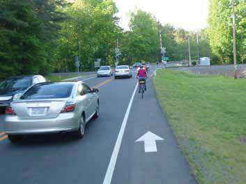
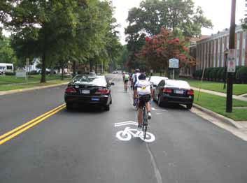
Wide outside lanes are 14 feet or greater in width to allow motorists to pass bicyclists without encroaching into the adjacent lane. These lanes may have shared lane markings present. Bike lanes are the preferred treatments on major roadways when sufficient width is available to provide them (AASHTO). Wide outside travel lanes on arterial roadways are generally acceptable for experienced cyclists, but less-experienced bicyclists may not feel comfortable on this type of facility.
Additional Considerations for the Placement of Shared Lane Markings
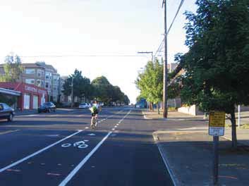
In general, shared lane markings are installed on streets where there is not enough space for bicycle lanes, or there is no desire for a bicycle lane. When bike lanes are desired but space limitations exist, a bike lane can be installed on one side of the street (i.e., the up-hill side of the street to provide dedicated space for slower, hill climbing bicyclists) and shared lane markings on the downhill side. Shared lane markings may be the first choice (even if there is room for a bicycle lane) on some downhill sections.
Consideration for Shared Lane Marking Placement within a Travel Lane
The placement of shared lane markings will require engineering judgment as lane widths, quantity of lanes, operating speeds and presence of parking will vary from street to street. In particular, the width of the shared travel lane and the number of available travel lanes impact typical operating behavior of motorists and bicyclists. Travel lanes with widths less than 13 feet will require motorists to partially or fully change lanes to pass bicyclists. Travel lanes of 13 feet or greater generally allow motorists to pass bicyclists with minimal or no encroachment into adjacent travel lanes, allowing 3 feet of horizontal separation between the motorist and bicyclist.
The center of shared lane markings should be located a minimum of 11 feet from the curb or edge of roadway at locations where parking is permitted adjacent to the travel lane. The center of shared lane markings should be located a minimum of 4 feet from the curb or edge of roadway at locations where parking is prohibited. The shared lane marking may be moved towards the center of the lane regardless of whether it is adjacent to parking or not.
It may be appropriate to move the shared lane marking towards the center of the travel lane (exceeding the MUTCD minimums) if engineering judgment determines that this placement will enhance the safety of the bicyclist operating within the travel lane. In most cases, it will be a combination of two or more of the following factors which will indicate that consideration should be given to moving the shared lane marking towards the center of the travel lane:
- Travel lane is less than 12 feet in width
- Speed of traffic (less than 35 mph)
- Number of travel lanes (it may be desirable to place the shared lane marking towards the center of a narrower outside travel lane when a center turn lane is present or when there are multiple travel lanes in the same direction)
- Grade of roadway and expected bicyclist speed (center lane placement often works well when going downhill on streets with grade and higher bicycle speeds)
- Volume of traffic (may or may not be an issue – speed, grade, and number of lanes are more important)
Situations Where Travel Lanes Are Less than or Equal to 12 Feet in Width
Shared lane markings should be placed in the center of the travel lane where travel lanes are less than 12 feet in width to encourage bicyclists to occupy the full lane and not ride too close to parked vehicles or the edge of the roadway. A BIKES MAY USE FULL LANE (R4-11) sign may be used to supplement the marking. Travel lanes of this dimension are too narrow for sharing side by side with vehicles.
Situations Where Travel Lanes Are Between 12 Feet and 13 Feet in Width
Where travel lanes are 12-13 feet in width, the travel lane can appear shareable to roadway users if bicyclists operate on the right side of the lane, resulting in unsafe passing maneuvers. It may be desirable to place the marking in the center or close to the center of the lane to discourage these behaviors. A BIKES MAY USE FULL LANE (R4-11) sign may be used to supplement the marking.
Situations Where Travel Lanes Are Greater than or Equal to 13 Feet in Width
Where travel lanes are 13 feet or wider, motorists will generally be able to pass bicyclists within the same lane or will only need to slightly encroach on adjacent lanes to pass bicyclists. The shared lane marking should generally be located in the right portion of the lane (per the MUTCD minimum requirements) with exceptions for locations adjacent to parking. A SHARE THE ROAD sign (W11 1 AND W16-1P) may be used to supplement the marking.
Shared lane markings should generally be used on arterial and non-arterial roadways with motor vehicle speeds 35 mph or less. Research has shown that placing the marking in the center of travel lanes wider than 13 feet will likely result in poor compliance by bicyclists who will travel in the right portion of the lane, which may undermine the effectiveness of shared lane markings in narrower lanes.
9 https://www.fhwa.dot.gov/publications/research/safety/pedbike/05138/
The positioning of the bicyclists, particularly longer bikes or bikes with trailers, and crossing times are important considerations for designing a crossing that can get cyclists across a busy roadway safely and comfortably. There are a number of intersection treatments available that can aid cyclists in crossing busy intersections including signalization, crossing islands, high visibility crosswalks and flashing warning beacons.
Many arterial streets are challenging to cross, particularly during peak travel periods. In order to make it possible for bicyclists to travel throughout campus, there must be safe places to cross major streets. The section below describes the types of treatments that are recommended to help bicyclists cross these major roadways. Selection of the appropriate roadway crossing treatment depends on a number of factors:
- Roadway width/number of lanes
- Motor vehicle traffic volumes
- Motor vehicle speed
- Sight-distance
- On-street parking
- Presence of traffic signals at the intersection or at nearby intersections
- Satisfaction of necessary and relevant traffic warrants
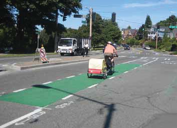
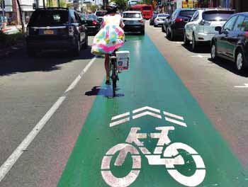
The use of contrasting color was issued Interim Approval status by FHWA on April 15, 2011. The use of contrasting green color has been shown through experimentation to increase awareness of bicyclists but has so far not been shown to reduce crash rates in conflict areas. A written request must be submitted to the FHWA in order to implement green color pavement.
Design guidance and application from the interim approval for contrasting pavement state:
- The color green is designated as the color for bicycle facilities. The material used for green color can be paint, colored asphalt or concrete or other marking materials with the proper chromaticity and slip resistance.
- Green pavement marking may be used within a bicycle lane or within an extension of a bicycle lane to enhance the conspicuity of the lane or extension.
- If a pair of dotted lines is used to extend a bicycle lane across an intersection or driveway, or a ramp, green colored pavement may be installed between these lines as a supplement to the lines.
Bicycle Signal Head
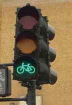 Bicycle signals heads can provide more clear direction to bicyclists crossing signalized intersections that they may enter an intersection. This is particularly important at locations where bicyclists may be provided an advance or exclusive phase. At locations (typically trail crossings) where cyclists are expected to follow pedestrian signals, under present law and timing practices, bicyclists may only “legally” enter the crosswalk during the solid WALK portion of the signal, the walkway portion is significantly shorter than the provided walk plus clearance time. This often results in bicyclists disobeying the flashing DON’T WALK portion of the cycle which can lead to them being caught in the intersection during the change interval. Providing bicycle signals allows for a longer display of green as compared to the walk, which significantly improves the compliance with the traffic control. Further, the MUTCD states explicitly that pedestrian signals are for the “exclusive use of pedestrians”. Bicycle signals can be designed to call a green signal phase through the use of loop detectors (or other passive detection such as video or radar) or push button. Bicycle signal heads and a separate bicycle signal phase should be considered at intersections and trail crossings with very high volumes of cyclists or locations where it is desirable to provide separate phasing for the bicyclists.
The MUTCD has no provision for bicycle signals; however bicycle signals were issued interim approval for use by FHWA in December 2013. The NCUTCD has developed draft language for inclusion into an interim approval for FHWA’s consideration.
Rectangular Rapid Flashing Beacons
The use of RRFB was issued Interim Approval status by FHWA on July 16, 2008 for the use at pedestrian crossings. Research has shown higher motorist yielding rates for RRFB versus standard flashing beacons. A written request must be submitted to the FHWA to participate in the Interim Approval. A written request to experiment with the device would be required for use at locations intended primarily for bicyclists.
Pedestrian Hybrid Beacons (a.k.a: HAWK Signal – High Intensity Activated Crosswalk)
Signal Timing and Bicycle Detection
It was observed that the majority of collector and local street crossings of arterials at UNC-CH required actuation. The Town updated all signalized locations to detect bicyclists and marked the sweet spot for bicyclists detection with the bike detection pavement marking. Based on email discussions with staff, the minimum green time provided for crossing arterials is typically 5-6 seconds with extension time provided as motor vehicles are detected. Yellow and red times totaling 4-6 seconds are provided at each location to allow a motor vehicle to clear the intersection. Should a bicyclist attempt to cross one of the town’s 7 lane arterials (approximately 90 feet), they may not clear the intersection within the time provided. Section 9D.02 of the 2009 MUTCD states: “On bikeways, signal timing and actuation shall be reviewed and adjusted to consider the needs of bicyclists.” Accommodating bicyclists at actuated intersections is one relatively cost-effective way in which a town can make significant strides to improve the safety and level of service provided to bicyclists.
- Timings at signalized intersections should be modified on a case-by-case basis to consider the specific needs of bicycles, which have slower acceleration and operating speeds than motor vehicles. A stationary, or “standing”, cyclist entering the intersection at the beginning of the green indication and a moving, or “rolling”, bicyclist approaching the intersection towards the end of the phase should be considered. The needs of standing cyclists can typically be accommodated by increasing the minimum green time on an approach, which is the current state of the practice. The needs of rolling cyclists require increases to the yellow and red times (change and clearance intervals), which may result in a slight loss of capacity at the intersection.
- The minimum green time should be adjusted such that the total phase duration (minimum green time plus yellow and all red times) is long enough for a bicyclist leaving the stop bar at the beginning of the green indication to clear the far side of the intersection. This time is referred to as the Bicycle Standing Time and is sufficient for a bicyclist to react, accelerate and cross the roadway before the conflicting crossing traffic receives a green indication.
- At intersections with arterial roads and a side street of lower classification, there may be concern about the impact to delay on the arterial when the side street minimum green time is increased (i.e. by 4 seconds as the worst case scenario) to accommodate the bicycle standing time. However, the changes to the minimum green time should have a little, if any, impact to the delay for motor vehicles on the arterial. During peak periods, the green time allocated for a minor approach typically increases over the minimum green time due to high demand on the minor street. During off peak periods, the loss of green time allocated to an arterial road will have little impact due to the lower traffic volumes on the arterial.
- Change and clearance intervals (i.e. yellow and red times) provided for motor vehicles may sometimes be sufficient for bicyclists. Generally, the yellow times used for motorists, typically between 3 and 6 seconds, are suitable for cyclists. However, it may be necessary to consider lengthening the red time depending upon posted speed limit, intersection width, bicyclist speed, roadway grade and red time used for motorists. The difference in clearance time between faster motorists and slower bicyclists is exaggerated by increased crossing distances and increased motorists speeds; therefore, it is more challenging to accommodate bicycles in the signal timing at wide, high-speed intersections. Bicyclists traveling uphill may have even slower speeds than typical, further increasing their crossing times and requiring longer change and clearance intervals. As indicated above, increasing red times may be challenging due to potential decreases in motor vehicle capacity, increases in red-light running and increases in motor vehicle crashes. If it is determined that increasing the change and clearance interval are not feasible, it is recommended bicycle signal heads be evaluated to stop bicyclists from entering the intersection prior to the onset of the yellow indication which would be intended for motorists.
BMG = BCTstanding – Y – Rclear
BMG = PRT + V/2a + (W + L)/V – Y – Rclear
where
- BMG = bicycle minimum green time (s)
- BCTstanding = bicycle crossing time (s)
- Y = yellow change interval (s)
- Rclear = all-red (s)
- W = intersection width (ft)
- L = typical bicycle length = 6 ft (see chapter 3 for other design users)
- V = bicycle speed crossing an intersection (ft/s)
- PRT = perception reaction time = 1 s
- a = bicycle acceleration (1.5 ft/s )
| Intersection Width* | Bicycle Standing Time** |
|---|---|
| 30 | 803 |
| 40 | 9 |
| 50 | 9.7 |
| 60 | 10.4 |
| 70 | 11.1 |
| 80 | 11.8 |
| 90 | 12.4 |
| 100 | 13.1 |
| 110 | 13.8 |
| 120 | 14.5 |
* Distance from Stop bar to far side of conflicting travel lane
**Assumes a 6 foot bicycle length and 10 mph operating speeds. Slower or faster operating speeds should be considered depending upon conditions (e.g. type of user, grade of road) at the intersection.
Crossing Islands
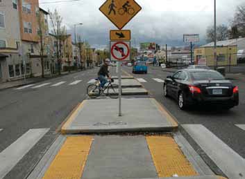 Crossing islands facilitate crossings of multiple lane and/or high-volume arterials by providing space in the center of the roadway. They allow the pedestrian or bicyclist to focus on one direction of traffic at a time (two-stage crossing). Median islands (or crossing islands) are constructed at the center of a road to physically separate the directional flow of traffic and to provide pedestrians and bicyclists with a place of refuge while reducing the crossing distance between safety points.
Arterial roadway intersections that have low demand for left-turn movements can be potential candidates for adding median islands. Median islands can be constructed on these roadways by using the available center turn lane area or by removing parking from one side of the street and shifting the travel lanes. Median islands are likely to be a medium- or long-term improvement on roadways where significant channelization changes are needed to provide enough space for the median island
The newest AASHTO Guide outlines design considerations for median crossing islands:
- Median islands are beneficial to install on roadways that have high traffic volumes, roadways that are too wide for full roadway crossing and roadways with more than three travel lanes.
- Minimum width for storage on the median is 6 feet. 10 feet accommodates a bike with trailer.
- Island should be large enough for multiple people to be on the island at once (e.g. strollers, bicyclists and pedestrians etc.)
- Angling the refuge area at approximately 45 degrees is recommended to direct those crossing to face towards on-coming traffic.
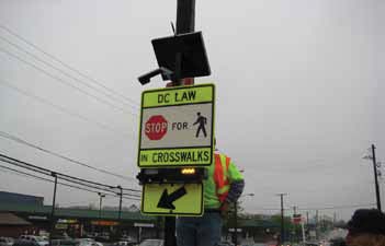
Advanced Yield Markings
Advanced yield markings in conjunction with “YIELD HERE TO PEDESTRIANS” signs have proven to be effective at reducing multiple threat crashes at uncontrolled, marked crosswalk locations. A multiple threat crash results when a car in one lane stops to let the pedestrian cross, blocking the sight lines of the vehicle in the other lane of a multi-lane approach which advances through the crosswalk and hits the crossing pedestrian(s). The MUTCD (2009) requires the use of “YIELD HERE TO PEDESTRIANS” (R1-5, R1-5a) signs if yield lines (shark’s teeth) are used in advance of a marked crosswalk that crosses an uncontrolled multi-lane approach. “YIELD HERE TO PEDESTRIANS” signs may also be used without the installation of advanced yield lines. If yield lines and “YIELD HERE TO PEDESTRIANS” signs are used in advance of a crosswalk, they should be placed together and 20 to 50 feet before the nearest crosswalk line; parking should be prohibited in the area between the yield line and the crosswalk. “YIELD HERE TO PEDESTRIANS” signs may be used in conjunction with the “PEDESTRIAN CROSSING” (W11-2) warning sign but must be on a preceding post and not block the road user’s view of the W11-2 sign. This application should be considered at trail crossings, pedestrian hybrid beacon crossings and bicycle boulevard crossings of arterials. It is recommended the bicycle symbol be incorporated onto the signs. If a pedestrian hybrid beacon is used at a crossing location, then a “CROSSWALK STOP ON RED” (R10-23) should be used per Section 2B.53 of the MUTCD.
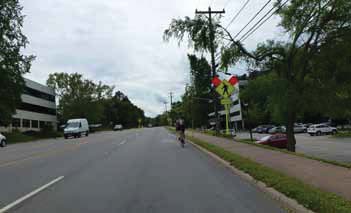
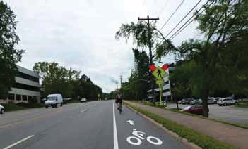
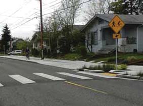
High-visibility Pedestrian/Bicycle Crossing Warning Signs
High-visibility bicycle and pedestrian warning signs are recommended at trail crossings. These signs can increase driver awareness of bicyclists and pedestrians, especially at mid-block locations where bicyclists and pedestrians may not be expected. These signs will be most effective when combined with other treatments, such as marked crosswalks, curb extensions and median islands, etc. Signs should be used judiciously—too many signs can cause visual clutter and lead to non compliance. High visibility bicycle and pedestrian signs are incorporated into the new MUTCD.
Crossings at Off-Set Intersections
Greater detail on all of these design treatments can be found in the documents mentioned above, as well as other sources such as PedSafe11 and the NACTO website.
- Locate rack a minimum of 36 inches from walls
- Provide a minimum of 36 inches between parallel racks
- Allow a minimum of 96 inches between end-to-end rows of u-racks to accommodate a pedestrian aisle